Product Page
INA219 Bi-direction DC Current Power Supply Sensor Module In Pakistan
₨ 580
[yith_wcwl_add_to_wishlist]
Need some help?
Contact Us
Product Ships in
2-3-business Days
Payment Methods:

INA219 Bi-direction DC Current Power Supply Sensor Module Gy-219 Module | microsolution.com.pk
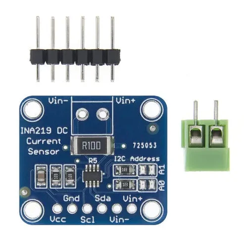
This INA219 breakout board will solve all your power-monitoring problems. Instead of struggling with two multimeters, you can just use the handy INA219B chip on this breakout to measure both the high side voltage and DC current draw over I2C with 1% precision.
Most current-measuring devices such as our current panel meter are only good for low side measuring. That means that unless you want to get a battery involved, you have to stick the measurement resistor between the target ground and true ground. This can cause problems with circuits since electronics tend to not like it when the ground references change and move with varying current draw. This chip is much smarter – it can handle high side current measuring, up to +26VDC, even though it is powered with 3 or 5V. It will also report back that high side voltage, which is great for tracking battery life or solar panels.
A precision amplifier measures the voltage across the 0.1 ohm, 1% sense resistor. Since the amplifier maximum input difference is ±320mV this means it can measure up to ±3.2 Amps. With the internal 12 bit ADC, the resolution at ±3.2A range is 0.8mA. With the internal gain set at the minimum of div8, the max current is ±400mA and the resolution is 0.1mA. Advanced hackers can remove the 0.1 ohm current sense resistor and replace it with their own to change the range (say a 0.01 ohm to measure up 32 Amps with a resolution of 8mA)
We include a 6-pin header (so you can easily attach this sensor to a breadboard) as well as a 3.5mm terminal plug so you can easily attach and detach your load. Usage is simple. Power the sensor itself with 3 to 5VDC and connect the two I2C pins up to your microcontroller. Then connect your target power supply to VIN+ and the load to ground to VIN-. We have an Arduino library right now that will do all the gain, range and math for you – just plug and go! We’ll have a more detailed tutorial up shortly.
Key Specifications
- Chip: INA219B
- Sense Resistor: 0.1 ohm, 1%, 2W current sense resistor
- Bus Voltage Range: 0V to +26V target voltage
- Current Measurement Range: Up to ±3.2A with a resolution of 0.8mA (or up to ±400mA with 0.1mA resolution using internal gain settings)
- Operating Voltage: 3.0V to 5.5V (powers the sensor board itself)
- Interface: I2C (supports 7-bit addresses
0x40,0x41,0x44,0x45selectable via jumpers)
Pinout and Connections
- VCC / VIN (Logic): Connect to 3V–5V from your microcontroller (like Arduino).
- GND: Ground connection.
- SDA / SCL: I2C data and clock lines to your microcontroller.
- VIN+ (or IN+): High-side positive power supply input from your target load/battery.
- VIN- (or IN-): Output connecting to the positive terminal of your load.
- What microcontroller are you using (e.g., Arduino, ESP32, Raspberry Pi)?
- What is the load or voltage you plan to monitor?