


8 Sensor Line Following Array in Lahore | MIcrosolution
Sensor Line Following Array in Lahore.
Setting the Jumpers
The array has two configurable options: I2C address and I2C pull-up voltage.
I2C address
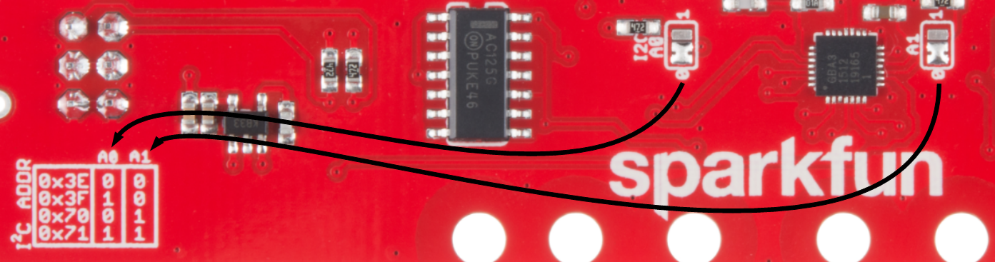
If you need to change the address of the array, move the solder jumper to set A0 and A1. The silkscreen table gives a reference. Seen in the photo, the default address is 0x3E. For example, if you want to use address 0x70, move A1 to the ‘1’ position and leave A0 at ‘0’.
[happyforms id=”5763″ /]
₨600
Compare8 Sensor Line Following Array in Lahore | MIcrosolution
This sensor module has 8 IR LED/phototransistor pairs mounted on a 0.375″ pitch, making it a great detector for a line-following robot. Pairs of leds are arranged in series to halve current consumption, and a MOSFET allows the LEDs to be turned off for additional sensing or power-savings options. Each sensor provides a separate digital I/O-measurable output.
Note: The QTR-8RC reflectance sensor array requires digital I/O lines to take readings.
Functional Description:
The QTR-8RC reflectance sensor array is intended as a line sensor, but it can be used as a general-purpose proximity or reflectance sensor. The module is a convenient carrier for eight IR emitter and receiver (phototransistor) pairs evenly spaced at intervals of 0.375″ (9.525 mm). Each phototransistor uses a capacitor discharge circuit that allows a digital I/O line on a microcontroller to take an analog reading of reflected IR by measuring the discharge time of the capacitor. Shorter capacitor discharge time is an indication of greater reflection.
The outputs are all independent, but the LEDs are arranged in pairs to halve current consumption. The LEDs are controlled by a MOSFET with a gate normally pulled high, allowing the LEDs to be turned off by setting the MOSFET gate to a low voltage. Turning the LEDs off might be advantageous for limiting power consumption when the sensors are not in use or for varying the effective brightness of the LEDs through PWM control.
The LED current-limiting resistors for 5 V operation are arranged in two stages; this allows a simple bypass of one stage to enable operation at 3.3 V. The LED current is approximately 20-25 mA, making the total board consumption just under 100 mA. The schematic diagram of the module is shown below
Specifications:
- Dimensions: 2.95″ x 0.5″ x 0.125″ (without header pins installed)
- Operating voltage: 3.3-5.0 V
- Supply current: 100 mA
- Output format: digital I/O compatible
- Optimal sensing distance: 0.125″ (3 mm)
- Maximum recommended sensing distance: 0.375″ (9.5 mm)
- Weight without header pins: 0.11 oz (3.09 g)
- QTR-1RC output (yellow) when 1/8″ above a black line and microcontroller timing of that output (blue).

Related products
-
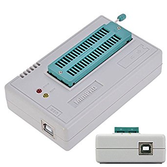
All MIcroSolution Pro, ARDUINO Nano
Arduino leonardo R3 in Pakistan
- ✅ Delivery Type: Free Shipping
- ✅ Payment Option: Cash on Delivery
- ✅ Return Policy: 7 Days Return Warranty
- ✅ Delivery Time: 24-48 Hours
- ✅ Rapid return on investment
- ✅ Environmentally friendly
- ✅ CALL NOW For Original Arduino leonardo R3 price in Pakistan Microsolution Hallroad lahore
SKU: n/a -
All MIcroSolution Pro
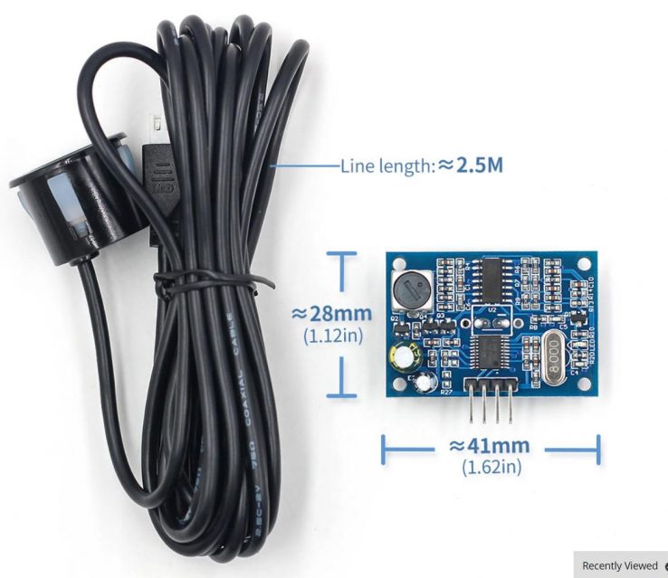
Waterproof ultrasonic sensor in Pakistan
Waterproof ultrasonic sensor in Pakistan | Microsolution Hallroad Lahore
- Delivery Type: Free Shipping
- ✅Payment Option: Cash on Delivery
- ✅Return Policy: 7 Days Return Warranty
- ✅Delivery Time: 24-48 Hours
- ✅Rapid return on investment
- ✅Environmentally friendly
- ✅CALL NOW For Original
SKU: n/a