Product Page
HLW8012 Energy Metering Module In Pakistan | microsolution.co
[yith_wcwl_add_to_wishlist]
Need some help?
Contact Us
Product Ships in
2-3-business Days
Payment Methods:

Hlw8012 High Precision Energy Metering Module Arduino Energy Monitoring
-
The HLW8012 High Precision Energy Metering Module is a single-phase AC energy monitor that tracks RMS voltage, RMS current, and active power. Popularized by its use in home automation products like the Itead Sonoff POW, it communicates with microcontrollers like Arduino or ESP8266 by converting measured electrical values into variable-frequency square wave pulses.⚠️ Critical Safety Warning
- High Voltage: This module requires invasive connection to 110V/220V AC mains power.
- No Isolation: Many basic breakout boards share a ground with the AC mains lines. Never plug your Arduino into a computer's USB port while the module is connected to live AC power unless your module features onboard optocouplers for isolation.
Module Pinout and Specifications
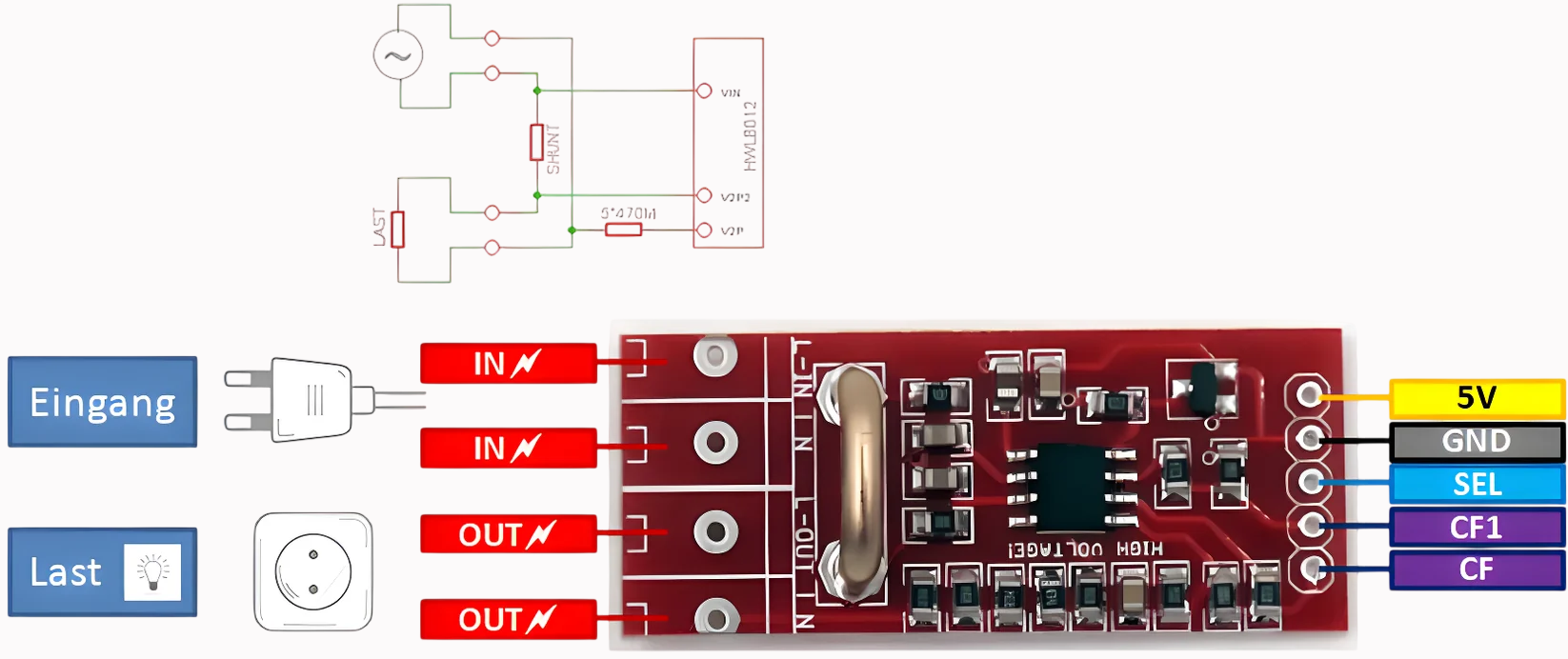
The module typically exposes 5 pins to interface with your Arduino:- VDD: 5V Power Supply input (consumes <3mA).
- GND: Signal Ground.
- SEL: Digital Input. Controls what output is transmitted on the CF1 pin.
- Set
SELLOW to read RMS Current on CF1. - Set
SELHIGH to read RMS Voltage on CF1.
- Set
- CF: Digital Output. Emits pulses proportional to Active Power (Watts).
- CF1: Digital Output. Emits pulses proportional to either Current or Voltage, depending on the
SELpin status.
Technical Highlights
- Active Power Accuracy: Within ±0.2% across a 1000:1 dynamic range.
- Voltage/Current Accuracy: Within ±0.5% across a 500:1 dynamic range.
- Measurement Type: Current is sampled via a low-resistance shunt resistor; voltage is sampled via a high-value resistor divider network.
Arduino Wiring Guide
To accurately decode the high-frequency pulses, theCFandCF1pins should connect to pins on your Arduino that support hardware interrupts (e.g., Pins 2 and 3 on an Arduino Uno).HLW8012 Pin Arduino Uno Pin Purpose VDD 5V Logic Power GND GND Common Ground SEL Pin 4 (or any digital GPIO) Selection Toggle CF Pin 2 (Interrupt 0) Active Power Reading CF1 Pin 3 (Interrupt 1) Current / Voltage Reading
Software Integration
Writing raw code to parse pulse frequencies can be tricky due to calibration requirements. It is highly recommended to use the open-source library maintained on the xoseperez HLW8012 GitHub Repository, or configure it using the native ESPHome HLW8012 component if you migrate to an ESP8266/ESP32 web platform.Basic Calibration ProcessBecause manufacturing tolerances affect shunt resistors and divider networks, you must calibrate the sensor once it is wired:- Connect a known pure-resistive load (such as a 100W incandescent light bulb).
- Measure your mains voltage using a reliable multimeter (e.g., 220V).
- Use the library's
targetcalibration functions to adjust the internal multipliers until the Arduino readout matches the known load's values.
If you'd like to proceed with your setup, tell me:- Which Arduino board model are you using?
- Does your specific module have onboard optocouplers for safe USB debugging?
- What is the maximum current (Amps) of the appliance you want to monitor?
I can provide a tailored wiring diagram and a ready-to-flash Arduino code sketch.