
Bluetooth home automation using 8051 microcontroller in pakistan. Leave a comment
Imagine that you can control the electronic appliances of your home from anywhere inside the house, just using your Smart phone. In this project, we will use wireless Bluetooth technology to control the Home Electronic Appliances through a Android Phone. Bluetooth has a range of 10-15 meters, so that you can switch ON and OFF any electronic appliance within the range. We have also developed a Toy car controlled by Android Phone, using Bluetooth module and Arduino.
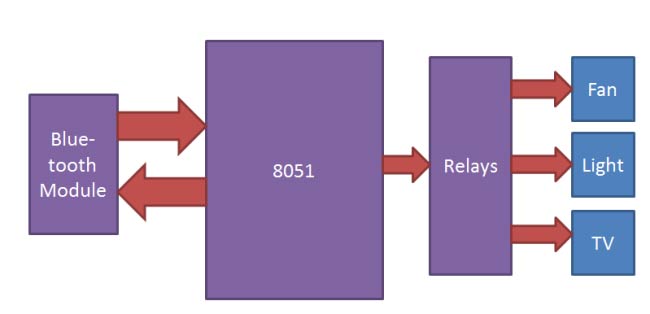
Here we have used 8051 microcontroller with a Bluetooth module, for wirelessly receive the data, sent from the Android Phone. So that microcontroller can Turn ON and OFF the home appliances accordingly. [Check here more 8051 microcontroller based projects]
Main Components
- 8051 microcontroller
- Bluetooth Module HC05
- Relay
- ULN2003
- Bulb
- Holder
- Wire
- IC 7805
- Android phone
- Bluetooth controller app Android app
- 10uf capacitor
- 1000uf capacitor
- 10K resistor
- 1k resistor
- Power Supply
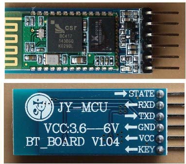
Bluetooth Module:
HC-05 Bluetooth module consists two things one is Bluetooth serial interface module and a Bluetooth adaptor. Bluetooth serial module is used for converting serial port to Bluetooth.
How to operate Bluetooth module?
You can directly use the Bluetooth module after purchasing from market, because there is no need to change any setting of Bluetooth module. Default baud rate of new Bluetooth module is 9600 bps. You just need to connect rx and tx to controller or serial converter and give 5 volt dc regulated power supply to module.
Bluetooth module has two modes one is master mode and second one is slave mode. User can set either mode by using some AT commands. Even user can set module’s setting by using AT command. Here is some commands uses are given:
First of all user need to enter AT mode with 38400 bps baud rate by pressing EN button at Bluetooth module or by giving HIGH level at EN pin. Note: all commands should ends with \r\n (0x0d and 0x0a) or ENTER KEY from keyboard.
After it if you send AT to module then module will respond with OK
AT → Test Command
AT+ROLE=0 → Slave Mode select
AT+ROLE=1 → Master Mode select
AT+NAME=xyz → Set Bluetooth Name
AT+PSWD=xyz → Set Password
AT+UART=<value1>,<value2>,<value3> → set Baud rate
Eg. AT+UART=9600,0,0
Pin Description of accelerometer:
- STATE → Open
- Rx → Serial receiving pin
- Tx → Serial transmitting pin
- GND → ground
- Vcc → +5volt dc
- EN → to enter in AT mode
Working Explanation:
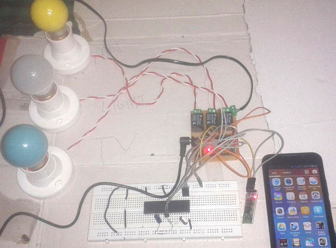
In this project we have used 8051 microcontroller for controlling the whole process of this project. And a Bluetooth module is used for controlling the home appliances wirelessly. Home appliances will turned ON and OFF when user will touch button in the Bluetooth mobile app in Android mobile phone. To run this project, first we need to download Bluetooth app form Google play store. We can use any Bluetooth app that can send data using Bluetooth. Here are some apps name that can be used:
- Bluetooth Spp pro
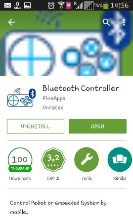
- Bluetooth controller
After installing the App, you need to open it and then search Bluetooth device and select HC-05 Bluetooth device. And then configure keys.
Here in this project we have used Bluetooth controller app.
- Download and install Bluetooth Controller.
- Turned ON mobile Bluetooth.
- Now open Bluetooth controller app
- Press scan
- Select desired Bluetooth device (Bluetooth Module HC-05).
- Now set keys by pressing set buttons on screen
To set keys we need to press ‘set button’ and set key according to picture given below:
After setting keys press ok.
You can see in the above picture that there are 9 buttons in which first row is for fan controlling, second one is for light controlling and last one is for TV controlling. Means First row’s ON and OFF buttons are used to ON and OFF the fan, second row’s buttons are for Light and third ones are for TV. We have used three bulbs of different colors instead of TV and fan, for demonstration purpose.
Now, when we touch any button in Bluetooth controller app then Android phone sends a value to Bluetooth module, after receiving this value, Bluetooth module sends the received value to the microcontroller and then microcontroller reads it and compare it with predefined value. If any match is occurred then microcontroller performs relative operation. Same operation will performed each time when button pressed.
Now, when user touch ‘Fan On’ button in Bluetooth controller app then microcontroller receives ‘1’ via Bluetooth module and then controller Switch ‘On’ the Fan by using relay driver and relay. And when user touch ‘Fan Off’ button in Bluetooth controller app then microcontroller receives ‘2’ via Bluetooth module and then controller Switch ‘Off’ the Fan by using relay driver and relay.
Likewise 3,4,5,6 numbers are sent by Android Phone, when Light On, Light Off, TV On, TV Off button has been touched respectively:
|
Button |
Data |
Operation |
|
Fan On |
1 |
Fan Turned On |
|
Fan Off |
2 |
Fan Turned Off |
|
Light On |
3 |
Light Turned On |
|
Light Off |
4 |
Light Turned Off |
|
TV On |
5 |
TV Turned On |
|
TV Off |
6 |
TV Turned Off |
Circuit Diagram and Explanation
Circuit connections of this project are very simple. Bluetooth module’s Rx and Tx pins are directly connected to the Tx and Rx pins of Microcontroller. Three 5 volt relays are used as a switch for turning On and Off the home appliances running on AC mains. And a relay driver ULN2003 is used for driving relays. Fan, Light and TV are connected at P2.1, P2.2 and P2.3 via relays and relay driver. An 11.0592 MHz Crystal oscillator is used in this circuit for generating clock signal for microcontroller. And a 5 volt voltage regulator LM7805 is used for provide 5 volt for the whole circuit.

Program Explanation:
In this program, first of all we have included header file and defines input, output pins and variables.
#include<reg51.h>

sbit Fan=P2^0;
sbit Light=P2^1;
sbit TV=P2^2;

 char str;
 char Charin=0;
After this we have created a function for delay.
void delay(int time)
{
  unsigned int i,j;
  for(i=0;i<time;i++)
  for(j=0;j<1275;j++);
}
Here we have some functions that we have used in our program. In this we have configured 9600bps baud rate at 11.0592MHz Crystal Frequency.
void Serialwrite(char byte)
{
  SBUF=byte;
  while(!TI);
  TI=0;
}
void Serialprintln(char *p)
{
  while(*p)
  {
    Serialwrite(*p);
    p++;
  }
  Serialwrite(0x0d);
}

void Serialbegin()
{
   TMOD=0x20;
   SCON=0x50;
   TH1=0xfd;
   TR1=1;
}
After this, in main program we have initialized UART and monitored the SBUF register for receiving the data. Then data is matched and compared with predefined values and relative operation has been performed.
void main()
{
  P2=0x00;
  Serialbegin();
  Serialprintln("System Ready...");
  delay(50);
  while(1)
  {
    while(!RI);
    Charin=SBUF;
    str=Charin;
    RI=0;
      if(str=='1')
      {
        Fan=1;
        Serialprintln(" Fan ON");
        delay(50);
      }
      else if(str=='2')
      {
        Fan=0;
        Serialprintln(" Fan OFF");
        delay(50);
      }
So that’s how we can create a whole system for the house and can connect all the AC appliances to the 8051 microcontroller using Relays. And this bluetooth controlled home automation system can be operated from a Smart phone.
#include<reg51.h>
sbit Fan=P2^0;
sbit Light=P2^1;
sbit TV=P2^2;
char str;
char Charin=0;
void delay(int time)
{
unsigned int i,j;
for(i=0;i<time;i++)
for(j=0;j<1275;j++);
}
void Serialwrite(char byte)
{
SBUF=byte;
while(!TI);
TI=0;
}
void Serialprintln(char *p)
{
while(*p)
{
Serialwrite(*p);
p++;
}
Serialwrite(0x0d);